I recently connected an Arduino to a Tri-Color LED Light Bar that I bought from SparkFun Electronics. I used pulse width modulation to control the brightness of each color. The individual colors combine to make the desired color. Download the code here and see the schematic below.
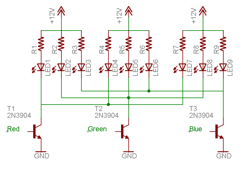
- R1–R9: Current limiting resistors soldered directly to the light bar. Using a multimeter, I determined that each resistor is about 453 ohms.
- LED1–LED9: Red, green, and blue LED’s contained in 3 superflux packages.
- T1–T3: The 2N3904 general purpose NPN transistors serve several purposes. First and foremost, the transistors increase the maximum current limit per color. Also, the transistors enable the Arduino’s smaller output voltage to switch a larger 12 volt source. Lastly, the LED’s are common anode. This means that the cathodes must be pulled low to turn on the LED’s. The transistors simplify the code in that positive logic is used instead.
I plan to buy more light bars, some higher current transistors, and a 12 volt power source for use on a larger scale.